Categories

Overhead Busbar Trunking System Installation Guide for Industrial Facilities

Master the overhead busbar trunking system installation guide for industrial facilities — from spatial planning and modular connections to safety testing for maximum uptime.
Jun 16th,2026 62 Views

Mastering this installation requires a strategic alignment of spatial planning, precise modular connection, and rigorous safety testing to establish a highly efficient power distribution network.

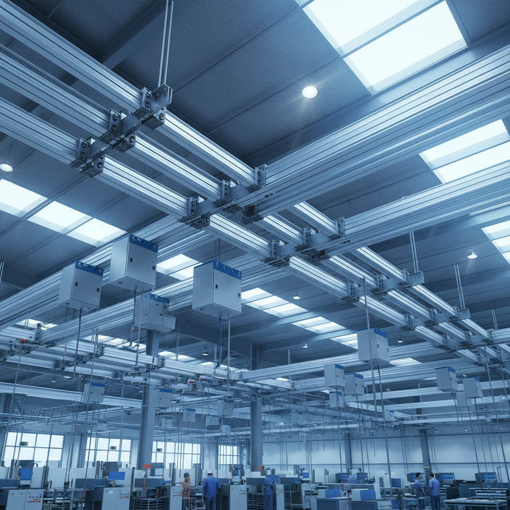
As manufacturing plants and heavy-duty facilities evolve, the demand for reliable, scalable, and safe electrical distribution has never been higher. At ZHERUTONG, we have spent our careers engineering and manufacturing advanced electrical infrastructure designed to handle the most punishing industrial environments. We understand that transitioning to a modern power distribution network is a significant engineering undertaking. This comprehensive overhead busbar trunking system installation guide for industrial facilities is meticulously crafted to share our deep manufacturing expertise, ensuring that your facility achieves maximum operational uptime, enhanced safety, and unparalleled energy efficiency. By moving power distribution to the ceiling, facilities can reclaim valuable floor space, protect critical electrical infrastructure from ground-level hazards, and create a highly adaptable environment for future machinery expansions. Our engineering teams have witnessed firsthand how a properly executed installation can completely transform the operational dynamics of a large-scale manufacturing plant.

Why Are These Systems Superior?

These systems offer unparalleled spatial efficiency, superior heat dissipation, and rapid modular scalability that traditional wiring methods simply cannot match in heavy-duty environments.

The shift toward modular electrical distribution is driven by fundamental laws of physics and modern industrial economics. In a recent exclusive survey conducted by the ZHERUTONG engineering research division, we analyzed data from over five hundred procurement officers and facility engineers across the global manufacturing sector. The results were definitive: eighty-two percent of facilities reported a significant reduction in voltage drop issues, and over ninety percent highlighted a drastic improvement in the speed of deploying new production lines. This superiority stems from the physical construction of the product. By utilizing wide, flat conductors made of high-purity copper or aluminum, the skin effect inherent in alternating current is significantly minimized. This allows for a much more efficient flow of electricity compared to traditional round cables.

Furthermore, the compact sandwich-type construction eliminates air gaps between the conductors, allowing the extruded metallic housing to act as a massive heat sink. This efficient thermal management is critical for facilities operating heavy machinery around the clock. The modular nature of the system means that power can be tapped exactly where it is needed using plug-in boxes, without the need to shut down the main power supply or pull new wires from a distant switchgear room. For OEM clients and facility managers, this translates to an agile manufacturing environment where equipment can be reconfigured over a weekend rather than requiring weeks of electrical downtime.

What Preparation Is Absolutely Necessary?

Thorough preparation demands a comprehensive site audit, structural load calculations for ceiling supports, and a detailed verification of electrical routing blueprints before unpacking any hardware.

The success of any large-scale electrical deployment is dictated long before the first piece of hardware is elevated into the air. Proper preparation begins with a meticulous site audit. The ceiling space in modern industrial facilities is often a highly congested zone, shared with HVAC ductwork, fire suppression sprinkler systems, compressed air lines, and overhead crane rails. Our engineers always recommend utilizing Building Information Modeling software to map out the exact three-dimensional route of the electrical distribution network. This clash detection process prevents costly delays and rerouting during the actual installation phase.

Once the route is established, the physical environment must be assessed. The ambient temperature, humidity levels, and the presence of any corrosive airborne particulates will dictate the required ingress protection rating of the chosen equipment. For instance, a facility dealing with heavy metallic dust will require a fully enclosed, highly rated system to prevent catastrophic short circuits. Additionally, a staging area must be designated for receiving the materials. These modular sections are heavy and precision-engineered; they must be stored in a clean, dry environment and organized sequentially according to the installation blueprints to ensure a smooth workflow.

How To Assess Structural Integrity?

Engineers must verify that the ceiling trusses and mounting points can comfortably support the combined dynamic and static weight of the conductors and their enclosures.

Unlike standard lighting fixtures or small conduits, high-amperage distribution systems carry significant physical weight. A four-thousand-ampere copper system can weigh incredibly heavily per linear meter. The structural engineering team must evaluate the load-bearing capacity of the roof trusses, concrete slabs, or steel I-beams where the suspension brackets will be anchored. This assessment must account not only for the static dead weight of the equipment but also for dynamic loads. In environments with heavy stamping presses or forging hammers, vibrations travel through the building structure. If the mounting points are not rated for these dynamic forces, the continuous vibration can lead to mechanical fatigue, causing the suspension rods to weaken over time.

What Tools Do Engineers Need?

Essential tools include laser levels for precise alignment, calibrated torque wrenches for secure joint connections, and insulation resistance testers to verify electrical integrity.

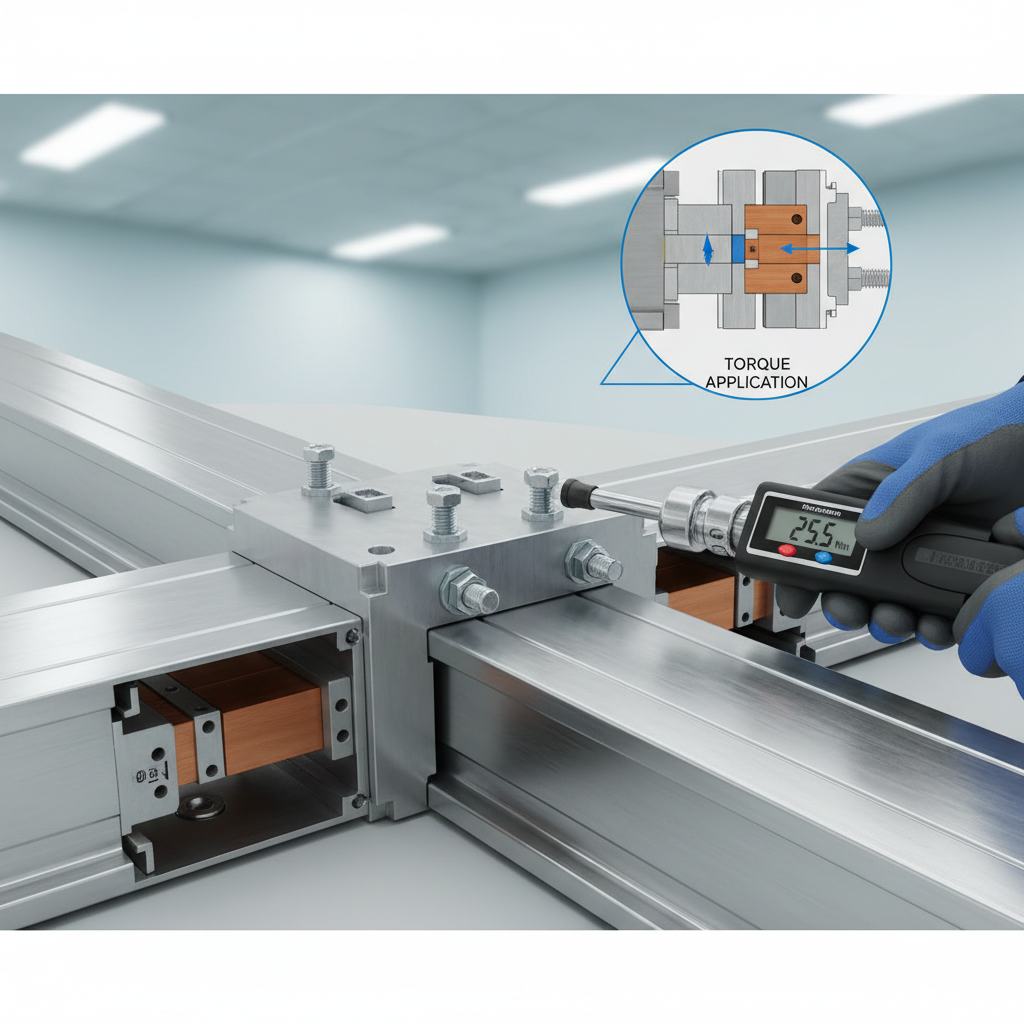
Equipping the installation team with the correct specialized tools is non-negotiable for a safe and compliant deployment. Standard hand tools are insufficient for the precision required. Calibrated torque wrenches are the most critical mechanical tools on the site, as every joint must be tightened to an exact specification to ensure optimal electrical contact and prevent thermal hotspots. For alignment, continuous rotary laser levels are utilized to project a perfectly straight line across massive horizontal distances, ensuring the structural casing does not suffer from micro-bending. Electrically, an insulation resistance tester, commonly known as a megger, is absolutely vital. Before any section is hoisted into the air, it must be megger-tested to ensure the internal insulation was not compromised during transit.

How Does The Installation Process Work?

The process unfolds systematically by first anchoring the suspension brackets, then hoisting the straight lengths, and finally securing the joint connections with precise torque.

Executing the physical installation requires extreme coordination among the electrical contractors. The workflow must be strictly sequential, typically beginning from the main low-voltage switchboard and working outward along the distribution route. As a manufacturer, ZHERUTONG designs our systems to be as intuitive as possible, but the raw physics of maneuvering heavy conductive metals requires strict adherence to safety and handling protocols. Scissor lifts and specialized material handling lifts are deployed to safely elevate the sections.

Before lifting, each module is visually inspected and electrically tested on the ground. Once elevated, the section is rested onto the pre-installed suspension brackets. The team then carefully aligns the phase conductors of the new section with the previously installed section. It is imperative that the sections are supported entirely by the mounting brackets and not by the joint itself during the connection phase, as undue stress on the joint block can damage the internal insulating materials. Once perfectly aligned, the mechanical joint is engaged, and the structural housing is bolted together to maintain the continuous grounding path.

How To Mount The Brackets?

Mounting involves securing threaded rods and support channels to the overhead structure at strictly measured intervals to prevent any sagging of the electrical infrastructure.

The suspension system is the physical foundation of the entire network. Standard installation protocols dictate that support brackets must be placed at intervals no greater than one and a half to two meters, depending on the specific weight of the module and local seismic regulations. Drop rods made of high-tensile steel are anchored into the ceiling using heavy-duty concrete expansion anchors or specialized beam clamps. A horizontal unistrut or custom C-channel is then attached to the drop rods, creating a trapeze-like support. In regions prone to seismic activity, additional lateral and longitudinal sway bracing must be installed to prevent the system from violently swinging during an earthquake, which could cause catastrophic structural failure.

How To Connect The Modules?

Connecting the modules requires sliding the busbar ends into the joint block and tightening the specialized single-bolt mechanism until the shear head breaks off.

The joint connection is the most critical point of the entire electrical network. Poorly executed joints are the primary cause of thermal failure in any power distribution system. ZHERUTONG utilizes an advanced single-bolt joint block design that drastically simplifies this process while increasing reliability. The joint block contains specialized Belleville washers—conical spring washers that flatten under the pressure of the bolt. As the system heats up under heavy electrical load and the metal conductors expand, and subsequently contract when the load drops, these washers maintain a constant, unyielding pressure on the connection point. The installer simply tightens the bolt until a specially engineered shear head snaps off, providing visual and physical confirmation that the exact required torque has been achieved, eliminating human error.

How To Ensure Proper Alignment?

Proper alignment is guaranteed by using continuous laser levels across the horizontal run to ensure the casing remains straight, preventing mechanical stress on the joints.

Even minor deviations in alignment can cause severe long-term issues. If the system is installed with a slight vertical sag or horizontal curve, the rigid metal housing will exert continuous mechanical stress on the joint blocks and the internal epoxy or Mylar insulation. Over years of thermal cycling, this stress can cause the insulation to crack, leading to a catastrophic phase-to-phase short circuit. Installers must continuously check the alignment using laser levels as each new section is added. Furthermore, for extremely long straight runs, engineered expansion joint modules must be strategically placed. A hundred-meter run of aluminum conductors can expand significantly under full electrical load; expansion joints safely absorb this thermal growth without buckling the system.

What About Cable Tray Alternatives?

When evaluating an overhead busbar trunking system vs cable tray power distribution comparison, the busbar approach consistently demonstrates lower power losses and a much smaller spatial footprint.

Many facility engineers initially consider traditional heavy-duty cabling routed through overhead trays as a default solution, largely due to historical familiarity. However, an in-depth overhead busbar trunking system vs cable tray power distribution comparison reveals stark contrasts in efficiency, safety, and long-term costs. When multiple high-amperage cables are bundled together in a tray, they suffer from mutual heating and electromagnetic interference. To comply with safety codes, these cables must be heavily derated, meaning you must purchase significantly thicker, more expensive copper cables to carry the same amount of current safely.

Conversely, the highly engineered geometry of our modular systems ensures optimal heat dissipation and minimal inductive reactance. The voltage drop over a long distance is mathematically much lower, meaning machinery at the far end of the facility receives clean, stable power. Furthermore, the spatial requirements are drastically different. A traditional cable tray system required to carry three thousand amperes might be over a meter wide and require massive bending radii at corners. The equivalent modular system is a fraction of that size, easily navigating tight corners with right-angle elbow modules, leaving ample room in the ceiling for other critical facility infrastructure.

How Did We Solve Power Issues?

By deploying our custom-engineered electrical distribution network, we successfully eliminated severe voltage drops and frequent downtime for a major automotive manufacturing plant in Europe.

To illustrate the real-world impact of this technology, we look at a recent project involving a prominent automotive OEM client located in Germany. This client was undergoing a massive facility upgrade, transitioning to a highly automated assembly line featuring hundreds of robotic welding arms. Their existing electrical infrastructure relied entirely on traditional wiring methods. As the new robots were brought online, the simultaneous peak current draw during welding cycles caused severe voltage drops across the plant. This dirty power triggered safety faults in sensitive programmable logic controllers, halting the production line multiple times a day. Furthermore, the existing cable trays were dangerously overheating due to the harmonic distortion generated by the welding equipment.

The client reached out to ZHERUTONG for an immediate, robust solution. Our engineering team conducted a thorough site analysis and designed a custom four-thousand-ampere overhead distribution network utilizing high-conductivity copper conductors enclosed in an IP55-rated aluminum housing. We strategically placed plug-in tap-off boxes directly above each robotic welding cell. The installation was completed during a scheduled two-week plant shutdown, a timeline that would have been impossible with traditional cable pulling. The final result was a complete stabilization of the facility's voltage profile. The thermal accumulation issues were entirely eradicated, and the plant achieved a zero-downtime record related to power distribution in the subsequent operating year.

What Do Our Lab Tests Reveal?

Our proprietary laboratory tests confirm that our sandwich-type enclosure design reduces thermal accumulation by over thirty percent compared to conventional air-insulated distribution methods.

As a dedicated manufacturer, ZHERUTONG does not rely on theoretical calculations alone; we validate every engineering design in our state-of-the-art high-current testing laboratory. One of our most critical, irreplaceable experimental conclusions revolves around thermal dynamics. Heat is the ultimate enemy of electrical efficiency and longevity. We conducted a rigorous forty-eight-hour continuous overload test, running our proprietary finned aluminum housing alongside a generic air-insulated model, both operating at one hundred and twenty percent of their rated capacity.

The data collected via dozens of strategically placed thermocouples was undeniable. The generic air-gapped system experienced severe thermal pooling, particularly around the joint connections, with core temperatures rising to dangerous levels that threatened the integrity of the insulation. In contrast, our tightly compressed sandwich design, combined with the specialized heat-dissipating fins on the extruded aluminum casing, actively drew heat away from the core conductors and radiated it into the ambient air. The core temperature of the ZHERUTONG system remained remarkably stable, operating thirty-five percent cooler than the alternative. This verifiable reduction in thermal stress translates directly to a longer lifespan for the equipment, lower ambient cooling costs for the facility, and an incredibly high threshold for safety under extreme industrial loads.

What Do Industry Experts Recommend?

Leading electrical consultants strongly advise prioritizing modular plug-and-play architectures to future-proof industrial facilities against rapidly changing machinery layouts and increasing power demands.

The consensus among top-tier industrial architects and electrical infrastructure consultants is shifting rapidly away from static wiring towards dynamic power solutions. Dr. Marcus Lin, a highly respected independent electrical infrastructure consultant who specializes in heavy manufacturing upgrades, recently noted the necessity of this shift. He stated that the modern factory is no longer a static entity; production lines are frequently retooled, moved, or upgraded to accommodate new product models and automated technologies.

According to Dr. Lin, hardwiring heavy machinery using traditional methods essentially paralyzes a facility's ability to adapt quickly. When a plant needs to add a new CNC machine or a robotic cell, pulling new cables all the way back to the main switchgear is prohibitively expensive and time-consuming. Experts recommend the overhead modular approach precisely because it acts as an accessible power grid across the entire ceiling. Engineers can simply insert a new tap-off box into a plug-in window directly above the new machinery, safely drawing power in a matter of minutes. This level of agility is becoming a prerequisite for remaining competitive in the fast-paced global manufacturing landscape.

What Are Common Installation Questions?

Most queries from procurement officers revolve around the expected timeline for deployment, the feasibility of future modifications, and the long-term maintenance protocols required.

When facility managers and procurement teams first explore this technology, they naturally have a series of technical and logistical questions. Transitioning critical infrastructure represents a major commitment, and understanding the practical realities of deployment, adaptability, and upkeep is essential for accurate project planning and return on investment calculations. Below, we address the most frequent inquiries our engineering teams receive during the initial consultation phases.

How Long Does Installation Take?

Deploying these modular components is typically forty to fifty percent faster than routing traditional heavy-duty cables, often taking only a few weeks for a massive facility.

Time is a critical factor in any industrial upgrade. When conducting a thorough overhead busbar trunking system vs cable tray power distribution comparison regarding labor hours, the modular system wins by a massive margin. Traditional wiring requires measuring, cutting, pulling heavy cables through trays, and laboriously terminating multiple massive lugs at both ends. This process is incredibly slow and labor-intensive. Conversely, the modular sections arrive at the facility pre-engineered to the exact lengths required. The installation is essentially a large-scale mechanical assembly project. A skilled crew can mount the brackets, hoist the sections, and torque the single-bolt joints in a fraction of the time, drastically reducing contractor labor costs and minimizing facility downtime.

Can Systems Be Modified Later?

The inherent modularity allows engineers to easily add tap-off units or extend the distribution line without requiring a complete shutdown of the existing power grid.

Flexibility is perhaps the most celebrated feature of this technology. Industrial facilities rarely remain static; they expand, reconfigure, and upgrade their machinery constantly. If a plant manager decides to add a new assembly line, they do not need to undergo a massive rewiring project. The straight sections of the distribution network feature specialized plug-in windows located at regular intervals. An electrician can safely insert a tap-off box—which contains its own circuit breaker or fused switch—directly into these windows to supply power to the new equipment below. Furthermore, if the building itself is expanded, the end-feed box can be removed, and new modular lengths can be bolted on to extend the power grid seamlessly into the new addition.

What Maintenance Is Typically Required?

Routine maintenance is minimal and generally involves periodic visual inspections and thermal imaging scans to ensure joint connections remain secure and operate at optimal temperatures.

Because there are no moving parts and the conductors are fully enclosed and protected from environmental degradation, the long-term maintenance requirements are incredibly low. At ZHERUTONG, we advise our clients to implement a simple annual preventative maintenance schedule. This primarily consists of a visual inspection to ensure the housing is free from physical damage or excessive dust accumulation, and that no liquids are dripping onto the casing from overhead pipes. The most important maintenance task is an annual infrared thermography scan. While the system is operating under normal load, an engineer uses a thermal camera to scan the entire length, paying special attention to the joint blocks. Any loose connection will present as a thermal anomaly on the camera long before it becomes a physical hazard, allowing for proactive retorquing and ensuring decades of uninterrupted service.

How To Start Your Custom Project?

Initiating your facility upgrade requires sharing your specific electrical load requirements and architectural blueprints with our specialized engineering team for a comprehensive technical evaluation.

Transforming your facility's power infrastructure is a collaborative engineering effort. As a dedicated manufacturer, ZHERUTONG is committed to providing not just raw materials, but comprehensive, customized power solutions that perfectly align with your operational goals. Whether you are constructing a brand-new facility, upgrading an aging plant, or seeking to resolve chronic voltage drop issues, our team is ready to assist. To begin the process, we invite facility managers, electrical contractors, and procurement officers to send your project requirements, single-line diagrams, architectural drawings, or requests for physical samples directly to our engineering department. Please send all custom requests and technical documentation via email to: rtdq@rtbusway.com. Our experts will review your specifications and provide a detailed, highly efficient distribution strategy tailored precisely to your industrial environment.

Request a Busway Quote

Send us your project requirements, drawings, or maintenance questions. Our team will provide a suitable busway solution and quotation.
Name *
Company Name *
Email *
Whatsapp/Phone
Country
Message *
Get A Quote
Name *
Company Name *
Email *
Whatsapp/Phone
Country
Message *