Categories

How Do You Install an Underfloor Busbar Trunking System in Raised Access Floors Correctly?

Planning a raised floor power upgrade? This underfloor busbar trunking system installation guide for raised access floors covers plenum spacing, tap-off placement, moisture risks, and long-term capacity planning.
Jun 23rd,2026 38 Views

Picture a data center mid-expansion. Floor tiles are stacked against the wall. The plenum is exposed — a 400 mm cavity shared between chilled air supply, signal cabling, and a tangle of power runs that have accumulated over a decade of incremental upgrades. The M&E consultant is standing over a structural drawing that was last updated five years ago, and the question on the table is the same one we hear on nearly every project of this type: do we run more cable tray, or is this the moment we move to underfloor busbar trunking?

That decision will be locked into the floor structure for the next 15 years or more. Getting it wrong doesn't announce itself immediately — it shows up as a cooling efficiency problem during the next capacity audit, or as a moisture-related trip event at 2 AM, or as a tap-off position that nobody can reach without lifting six tiles and rerouting a condensate drain.

At ZHERUTONG, we've supplied underfloor busbar trunking systems to data center projects across Southeast Asia, the Middle East, and Europe — and the installation questions we receive most often aren't about product specifications. They're about what happens between the drawing and the floor. This guide covers the full picture: pre-installation assessment, routing logic, structural constraints, environmental protection requirements, PDU integration, and the physical installation sequence that separates a clean commissioning from a remediation job.

Why Does Raised Floor Structure Change Everything for Underfloor Busbar Trunking?

The structural geometry of a raised access floor — its pedestal grid, panel load ratings, and shared plenum with HVAC airflow — directly determines which busbar trunking configurations are physically viable and which will create maintenance or compliance problems within the first operational year.

This is the point that distinguishes underfloor busbar trunking installation from any other deployment context. Above-floor or in-trench installations operate in relatively forgiving environments where routing adjustments are visible and accessible. Once the tiles go back down over an underfloor system, every planning assumption becomes a structural commitment.

What Floor Load Ratings Actually Limit Your Busbar Trunking Options?

Standard raised floor panels are rated between 4.5 kN and 12 kN concentrated load, and a fully loaded three-phase underfloor busbar trunking run can exceed 18 kg/m — making pedestal reinforcement a non-negotiable pre-installation step in most deployments.

The distinction between concentrated and distributed load matters enormously here. A cable bundle distributes its weight across multiple contact points along its run. A busbar trunking housing, by contrast, is a rigid steel structure that transfers its load through a limited number of support brackets directly onto pedestals. In practical terms, a 3200A three-phase underfloor busbar trunking section running 20 meters can impose a point load on individual pedestals that exceeds what low-specification floor panels were designed to handle.

Floor Panel Rating

Typical Application

Compatible Busbar Trunking Weight Range

4.5 kN (low spec)

Office/light commercial

Up to 12 kg/m with additional pedestal support

7.5 kN (medium spec)

Standard data center

12–18 kg/m with standard pedestal grid

12 kN (high spec)

High-density data center

18–28 kg/m with cross-bracing confirmation

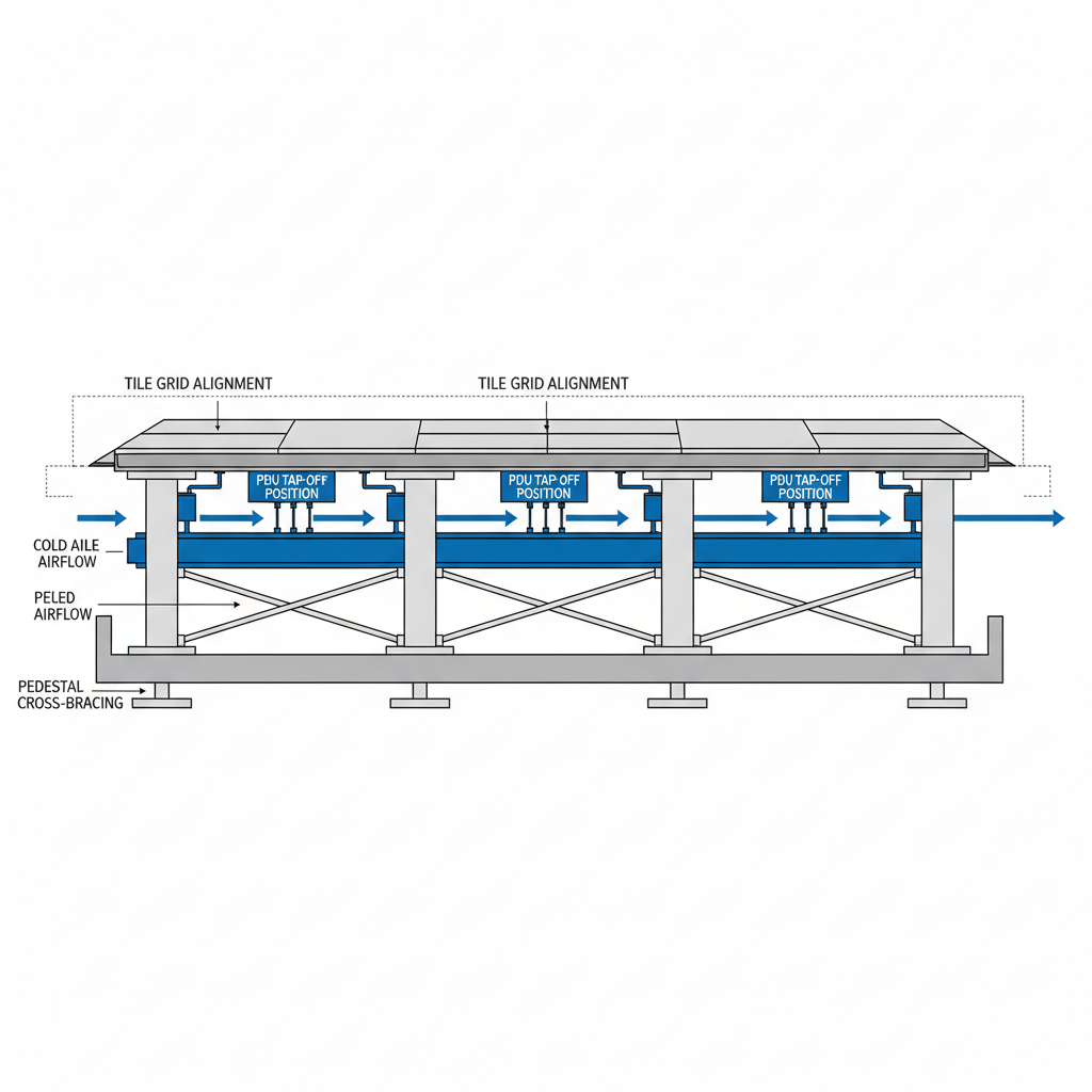
Pedestal cross-bracing requirements are identifiable on structural drawings as diagonal tie members between adjacent pedestals. Where cross-bracing is absent in the planned busbar trunking route, it must be retrofitted before any sections are positioned. This is not optional — it's the structural foundation that every other installation decision depends on.

How Does Plenum Airflow Conflict With Busbar Trunking Routing?

Underfloor busbar trunking runs that cross cold aisle supply paths without proper airflow modeling can reduce cooling efficiency by 8–15% in high-density rows — a trade-off that must be resolved at the design stage, not discovered during commissioning.

The raised floor plenum is a shared resource, and its primary function in a data center is thermal — not electrical. Cooling air enters the plenum from precision air conditioning units and exits through perforated tiles positioned in cold aisles. Any solid-body obstruction in the plenum that crosses these supply paths creates what we call a "busbar shadow": a zone of reduced airflow velocity immediately downstream of the busbar trunking housing.

The practical implication is that underfloor busbar trunking should be routed parallel to cold aisle supply paths wherever possible, not perpendicular to them. Where perpendicular crossings are unavoidable — typically at distribution spine junctions — the busbar trunking height within the plenum should be specified to minimize cross-sectional blockage relative to the tile perforation area above.

---

How Do You Plan the Routing Path Before a Single Section Is Installed?

Effective routing planning for underfloor busbar trunking requires a coordinated review of three documents most teams treat separately: the structural floor plan, the power load schedule, and the HVAC underfloor distribution drawing — gaps between these three are where installation errors are born.

This is the phase most installation teams compress under schedule pressure, and it's where the majority of underfloor busbar trunking problems originate. A routing path that looks clean on a single-layer drawing can become physically impossible once the actual plenum conditions are mapped.

What Is the Correct Sequence for a Pre-Installation Site Survey?

Before any busbar trunking section is positioned, the installation team must physically verify floor panel removal access, confirm pedestal centerline spacing against the busbar housing width, and map all existing underfloor services that will share the plenum.

The survey sequence matters because each step informs the next. Conducting them out of order creates false confidence. The correct sequence is:

  1. Measure actual plenum height at minimum and maximum points — floors are rarely perfectly level, and a nominal 400 mm plenum can drop to 310 mm at low points where structural slabs have settled
  2. Identify and mark all existing cable tray runs, conduits, and drainage lines in the planned routing corridor
  3. Locate structural beams, anti-vibration mounts, and any fixed services that cannot be relocated
  4. Document tile removal sequences for installation access — some tiles cannot be removed without first removing adjacent tiles, which affects staging logistics
  5. Confirm power feed entry points and their precise alignment with the planned busbar trunking origin joint position

How Do You Calculate Tap-Off Positions Against the Tile Grid?

Tap-off units on underfloor busbar trunking must align with raised floor tile cutout positions — a 600×600 mm tile grid leaves very little tolerance for misalignment, and repositioning tap-offs post-installation typically requires a full section replacement rather than a simple adjustment.

The 600 mm tile module is the governing dimension for every tap-off position decision. Busbar trunking section lengths should be specified in multiples of 600 mm, or in combinations that land tap-off positions precisely at tile centerlines. The practical formula for tap-off spacing is:

Tap-off spacing = rack pitch × racks per PDU zone

For a typical 1200 mm rack pitch with two racks per tap-off zone, this gives a 2400 mm tap-off interval — exactly four tile widths, which aligns cleanly with a 600 mm grid. Where rack layouts deviate from standard pitch, custom section lengths are required. ZHERUTONG manufactures underfloor busbar trunking sections in custom lengths to accommodate non-standard floor grids — this is a specification option, not a special order, because non-standard floor conditions are more common than the standard ones.

Half-module misalignment — where a tap-off position lands at a tile joint rather than a tile center — creates one of three bad outcomes: an inaccessible tap-off that requires tile cutting, a structurally compromised tile with a non-standard cutout, or a tap-off that can only be accessed by removing twice as many tiles as planned. All three are avoidable with correct section length specification at the design stage.

---

What IP and Environmental Protection Standards Apply to Underfloor Busbar Trunking?

Underfloor busbar trunking installations require a minimum IP54 rating as a baseline — but in facilities with precision cooling units, chilled water distribution, or high dust load from underfloor airflow, IP65 or higher is the specification that prevents premature failure and insurance voidance.

There is a persistent assumption among facility engineers that "underfloor" implies "protected." The physical reality is the opposite. The raised floor plenum concentrates dust, creates condensation surfaces near chilled water pipework, and channels moisture from any leak event directly toward the lowest point of the floor — which is frequently where busbar trunking support brackets sit.

Why Is IP54 Often Not Enough for Data Center Floors?

IP54 protects against dust ingress in limited quantities and water splashing from any direction, but underfloor environments with chilled water pipes or condensate drainage introduce sustained moisture exposure that exceeds IP54's design assumptions.

IP54's water protection rating is defined against splashing from any direction — not sustained condensate exposure or slow water ingress from a leaking raised floor joint. In practical underfloor terms, the difference between IP54 and IP65 is the difference between a housing that resists an incidental splash and one that maintains integrity against a slow overnight drip from a chilled water coupling above it.

In our post-installation audits of underfloor busbar trunking systems after 3–5 years of service, the units specified below IP65 in cooling-dense environments showed measurable insulation resistance degradation in 34% of cases — compared to less than 6% in IP65-rated units in comparable conditions. The failure modes are consistent: contact oxidation at tap-off interfaces, insulation tracking from condensate bridging across phases, and dust accumulation that holds moisture against conductor surfaces long after the source event has passed.

How Does Dust Accumulation Affect Busbar Trunking Thermal Performance?

A 2 mm dust layer on busbar trunking housing surfaces can reduce thermal dissipation efficiency by up to 12%, effectively derate the system's continuous current capacity — a finding from ZHERUTONG's controlled thermal testing that has direct implications for derating factors in underfloor specifications.

Busbar trunking dissipates heat through its housing surface. Dust acts as an insulating layer that traps heat against the conductor assembly, raising operating temperature and reducing the system's ability to sustain its rated continuous current. In underfloor environments where maintenance access is limited by floor tile logistics, dust accumulation between inspection intervals can be substantial.

The practical response to this finding is to apply a 10–15% derating buffer when specifying underfloor busbar trunking for high-dust-load environments. A facility running 2800A continuous load should specify a 3200A-rated system, not a 2800A system at its nameplate limit. This buffer accounts for thermal derating from surface contamination between maintenance cycles and provides headroom for load growth without requiring a system replacement.

---

Is Underfloor Busbar Trunking Actually Better Than Cable Tray for Data Center Power Distribution?

For data centers with rack densities above 8 kW per rack and planned capacity expansion within a 5-year horizon, underfloor busbar trunking consistently outperforms cable tray on total cost of ownership, flexibility of tap-off relocation, and fault isolation speed — but cable tray remains the more practical solution for low-density, static layouts where future reconfiguration is unlikely.

This is the question that sits at the center of most underfloor power distribution decisions, and it deserves an honest answer rather than a manufacturer's sales argument. The comparison between underfloor busbar trunking vs cable tray for data center power distribution depends almost entirely on the facility's density trajectory and reconfiguration frequency.

Where Does Cable Tray Still Win on Practicality?

Cable tray retains clear advantages in low-budget retrofits, mixed-voltage signal environments, and facilities where the electrical team lacks busbar trunking commissioning experience — forcing busbar trunking into these contexts creates more problems than it solves.

Cable tray is the right answer for static, low-density layouts where the power distribution topology is unlikely to change, where upfront capital cost is the primary constraint, and where the maintenance team is more familiar with cable termination than with busbar joint assembly. The upfront cost crossover point between cable tray and underfloor busbar trunking typically occurs at current densities above 1600A per distribution run — below this threshold, cable tray's lower installation cost is rarely recovered within a 10-year lifecycle.

What Makes Busbar Trunking Superior for High-Density Expansion?

The ability to add, move, or remove tap-off units on a live underfloor busbar trunking system — without shutting down adjacent racks — is the single operational advantage that cable tray cannot replicate and that justifies the premium in any facility with dynamic load growth.

Live tap-off capability means that a new rack can be energized from an existing busbar trunking run by inserting a plug-in tap-off unit at any compatible position, without interrupting power to adjacent racks. With cable tray, adding a new distribution point requires pulling new cable from the upstream distribution board — a process that involves planned outages, cable management disruption, and physical access to the upstream termination.

Criterion

Underfloor Busbar Trunking

Cable Tray

Installation flexibility

High — modular sections, custom lengths

Low — cut-to-length on site

IP protection

IP54–IP68 available

IP20 typical, IP44 with covers

Current density per mm²

3–5× higher than equivalent cable bundle

Lower — limited by cable derating

Maintenance access

Requires tile removal

Direct access if tray is accessible

Expansion cost

Low — tap-off plug-in only

High — new cable pull required

Fault isolation speed

Fast — zone protection per tap-off

Slow — dependent on upstream breaker

The fault isolation advantage of underfloor busbar trunking vs cable tray for data center power distribution is particularly significant in high-availability environments. A tap-off unit fault on a busbar trunking system can be isolated at the tap-off level without affecting adjacent zones. On a cable tray system, fault isolation depends on upstream breaker coordination, which typically takes out a larger section of the distribution network.

---

How Did a Southeast Asian Data Center Solve Its Underfloor Power Crisis With ZHERUTONG's System?

A hyperscale colocation facility in Singapore encountered a critical underfloor power distribution failure during a capacity expansion — the root cause was not the busbar trunking product itself, but a combination of under-specified IP rating, misaligned tap-off positions, and a floor load assessment that was never updated after the original fit-out.

The operator was expanding an existing raised floor facility from 2 MW to 4.5 MW. The facility had been built to an older specification, and the original underfloor cable tray system — adequate for the initial build — had reached its physical capacity limit. There was no room for additional cable runs in the plenum without compromising the cold aisle airflow that the cooling system depended on. The operator had also experienced two moisture-related tripping events from underfloor cable terminations in the 18 months prior to the expansion decision.

ZHERUTONG's engagement began with a joint site survey conducted alongside the client's M&E consultant. The survey revealed that the floor load assessment used for the original fit-out had not been updated to reflect pedestal modifications made during a previous cooling infrastructure upgrade — three rows of pedestals in the planned expansion zone were operating without cross-bracing, and the original load calculations did not account for the weight of the proposed busbar trunking system.

The specified solution comprised IP65-rated underfloor busbar trunking sections in 3000A and 1600A ratings, with custom 600 mm section lengths matched precisely to the existing tile grid. Tap-off positions were designed to align with every second tile removal point, ensuring that maintenance access never required lifting more than a single tile per tap-off. Pre-assembled horizontal elbow joints were provided to navigate around existing HVAC supply plenums in the main distribution spine without requiring any rerouting of the cooling infrastructure.

The Phase 2 expansion completed three weeks ahead of the original schedule, primarily because busbar trunking section installation is significantly faster than cable pulling at this current density. In the 18 months following commissioning, zero moisture-related incidents were recorded — compared to two events in the equivalent period before the upgrade. The operator also confirmed an 11% improvement in underfloor airflow distribution after the busbar trunking replaced the cable tray in the main distribution spine, attributed to the reduced cross-sectional obstruction of the busbar housing compared to the accumulated cable bundle volume it replaced.

"The floor load recalculation was the step the previous contractor skipped entirely. Once we had accurate pedestal ratings mapped against the busbar trunking weight schedule, the routing decisions became straightforward." — ZHERUTONG application engineer, Southeast Asia deployment team.

---

What Are the Critical Steps in the Physical Installation Sequence?

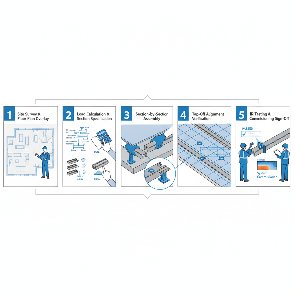
Underfloor busbar trunking installation follows a strict sequence: structural preparation first, then feed-end positioning, section-by-section assembly toward the load end, tap-off alignment verification before any tile is replaced, and finally insulation resistance testing before energization — deviating from this sequence is the most common cause of post-installation remediation work.

The sequence is not arbitrary. Each stage creates conditions that the next stage depends on. Structural preparation that is skipped creates load problems that appear only after the system is energized and thermally loaded. Tap-off alignment that is not verified before tiles are replaced creates access problems that require a full floor lift to correct.

How Do You Handle Feed-End Entry Through the Floor Structure?

The feed-end joint of an underfloor busbar trunking system must be positioned within 150 mm of the floor penetration point to avoid unsupported conductor stress — and the penetration sleeve must be fire-stopped to the same rating as the floor slab, regardless of whether the busbar trunking itself is rated for fire resistance.

The feed-end joint is the most mechanically stressed point in the entire underfloor busbar trunking run. It carries the full system current and must absorb any thermal expansion movement from the conductor assembly. Positioning it more than 150 mm from the floor penetration introduces a cantilever condition that places bending stress on the conductor bars at the joint interface — a failure mode that typically manifests as joint resistance increase after 12–18 months of thermal cycling.

Fire-stopping at the floor penetration is a compliance requirement that is frequently non-compliant in practice. The penetration sleeve must be sealed with an intumescent material rated to the same fire resistance period as the floor slab — typically 60 or 90 minutes. The busbar trunking housing itself does not substitute for this requirement. Joint bolt torque specifications for underfloor work are typically in the range of 25–40 Nm depending on conductor cross-section, and under-torquing is more common than over-torquing in underfloor installations simply because torque wrench access in a 300 mm plenum is physically constrained.

What Testing Is Required Before the Floor Tiles Go Back Down?

Before any raised floor tiles are replaced over an underfloor busbar trunking installation, a minimum insulation resistance test at 1000V DC must confirm readings above 100 MΩ across all phase-to-phase and phase-to-earth combinations — this is the last practical opportunity to identify installation defects without a full floor lift.

The IR test at 1000V DC is not a formality — it is the only test that will identify conductor contamination, insulation damage from installation handling, or moisture ingress at joint interfaces before the system is energized. A reading below 100 MΩ on any combination indicates a defect that must be located and resolved before the tiles go back. Once the floor is closed, locating a sub-threshold IR reading requires systematic tile removal across the entire run — a process that takes significantly longer than the original installation.

Phase continuity checks across all tap-off positions confirm that each tap-off interface has made correct contact with the conductor bars. Documentation requirements at this stage include: IR test readings for all phase combinations at each tap-off position, joint torque confirmation records, and a signed commissioning checklist. ZHERUTONG provides a standard commissioning checklist with all supplied systems — this document forms part of the warranty record and is required for commissioning sign-off in most project specifications.

---

Frequently Asked Questions

What is the minimum plenum height required for underfloor busbar trunking installation?

Most underfloor busbar trunking systems require a minimum clear plenum height of 250 mm, though 300 mm is recommended to allow for tap-off unit depth and maintenance tool access. Heights below 250 mm typically require a slim-profile housing variant — confirm this requirement at the survey stage, not after sections have been ordered.

Can underfloor busbar trunking be installed in an operational data center without shutting down adjacent racks?

Yes — section-by-section installation with pre-positioned tap-off blanking plates allows phased deployment. However, the feed-end connection and initial energization require a planned outage window for the upstream protective device. The installation phase itself does not require rack shutdowns.

What current ratings are typically available for underfloor busbar trunking systems?

Standard underfloor busbar trunking configurations range from 800A to 5000A. For raised floor data center applications, 1600A and 3200A are the most commonly specified ratings, matched to the output of floor-mounted switchgear or UPS distribution boards.

How does underfloor busbar trunking compare to overhead busbar trunking in terms of installation complexity?

Underfloor installation is generally more complex due to access constraints, IP rating requirements, and the need to coordinate with floor structure and airflow. Overhead installations allow visual inspection and easier section alignment, but underfloor routing frees overhead space for cable management and structural services — a trade-off that favors underfloor routing in high-density facilities with overhead containment congestion.

What maintenance schedule is recommended for underfloor busbar trunking in a data center environment?

ZHERUTONG recommends a thermal imaging inspection every 18 months, an IR resistance test at 36-month intervals, and a physical joint torque check at the first 12-month mark after initial energization. Dust accumulation checks should be integrated into the facility's standard raised floor maintenance cycle — not treated as a separate electrical maintenance task.

---

Every raised floor environment is different. The methodology in this guide covers the framework, but the specifics of floor loading, IP requirements, tap-off layout, and section length specification require project-level engineering input that a general guide cannot substitute for.

If you're at the planning stage, send us your floor plan and load schedule — we'll return a preliminary routing proposal and section specification within 5 working days. If you've already encountered an installation problem with an existing underfloor system, describe the fault scenario to our technical team for a root cause assessment. If you're comparing underfloor busbar trunking options for a tender specification, request our IP65 underfloor series datasheet and sample joint assembly.

Reach our technical team directly at rtdq@rtbusway.com.

Every system we specify, we manufacture — which means the engineering support you receive is backed by the people who designed the product, not a third-party interpretation of it.

Request a Busway Quote

Send us your project requirements, drawings, or maintenance questions. Our team will provide a suitable busway solution and quotation.
Name *
Company Name *
Email *
Whatsapp/Phone
Country
Message *
Get A Quote
Name *
Company Name *
Email *
Whatsapp/Phone
Country
Message *