Most installation failures in high-density data center busway projects don't happen during physical mounting — they happen in the decisions made weeks before the first bracket goes up. At ZHERUTONG, we've supported engineers and procurement teams across dozens of high-density deployments, and the pattern is consistent: facilities that skip structured pre-installation planning end up with phase imbalance issues, tap box conflicts with cold aisle containment, or busway runs that can't accommodate future capacity upgrades without a full teardown.
This guide is not a definition article. It won't explain what a data center busway is from scratch. Instead, it walks through the actual installation sequence — from structural height selection and feed unit positioning, through phase sequence planning and tap box spacing, to final commissioning checks — with specific attention to the constraints that high-density rack environments (20 kW/rack and above) introduce that standard-density installations simply don't face.
High-density data center rows — typically those running 20 kW per rack and above — impose thermal, structural, and capacity constraints that make standard busway installation sequences inadequate; phase loading imbalance and tap box interference with hot/cold aisle containment become real failure modes, not theoretical ones.
Engineers who have previously specified data center busway for general compute environments at 8–12 kW per rack often carry assumptions into high-density projects that simply don't hold. The ampacity margins are tighter, the overhead space is more contested, and the consequences of a miscalculation are harder to reverse once the facility is live. Understanding exactly where the constraints shift is the prerequisite for everything that follows.
Above 20 kW per rack, the cumulative current draw across a row can push a single busway run toward its rated ampacity ceiling faster than most installation teams anticipate, especially when redundancy (A+B feeds) is factored in.
Consider the math directly: a 10-rack row at 20 kW average draw on a 208V three-phase supply approaches approximately 555A per phase before any diversity factor is applied. That figure alone forces a choice between higher-ampacity busway in the 630A–800A range or splitting the row into shorter, independently fed runs. Neither option is free — higher-ampacity busway costs more and weighs more, while split runs require additional feed units and upstream switchboard breakers.
There is also a distinction that installation teams frequently collapse: installed capacity versus available capacity. A 630A-rated busway trunk does not mean 630A is simultaneously available at every tap box position. The conductor bars carry the cumulative load of all tap boxes, so the available capacity at any given tap box is the trunk rating minus the sum of all upstream tap box loads. In a fully populated high-density row, this margin can be uncomfortably thin before the row is even at full utilization.
GPU and AI server power supplies introduce an additional variable: power factor. Many high-performance compute PSUs operate at 0.90–0.95 power factor, which means true current draw is higher than a simple watts-to-amps calculation suggests. A 20 kW server load at 0.92 PF draws approximately 60A on a three-phase 208V circuit — not the 55A that a unity power factor assumption would produce. Across a 10-rack row, that difference accumulates to roughly 50A of additional current that an under-specified busway trunk was never sized to handle.
By contrast, a standard 8–12 kW/rack deployment on the same 208V three-phase supply draws roughly 22–33A per rack, leaving substantial headroom in even a 400A trunk. The engineering decisions that are optional at that density become mandatory above 20 kW.
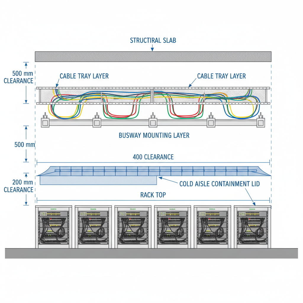
Cold aisle containment structures — particularly hard-lid ceiling panels — directly compete for overhead space with the busway run, and resolving this conflict requires coordinating mounting heights before either system is ordered, not after delivery.
The vertical arithmetic is unforgiving. Hard-lid containment ceiling panels typically sit at 2.1–2.4m above finished floor. Busway support brackets and the busway housing itself require 150–200mm of clearance above the containment lid to allow tap box installation and future access. Structural ceiling height becomes a hard upper boundary. In facilities where the structural slab sits at 3.0m above finished floor, the workable zone for the busway run may be as narrow as 400–500mm — and that same zone is competing with cable tray, sprinkler heads, and HVAC distribution.
This is a procurement-phase decision, not an installation-phase fix. Once the containment system is ordered to a specific height and the busway is ordered to a specific length with support bracket specifications, changing either requires reordering components, extending lead times, and in some cases redesigning the overhead layout entirely. At ZHERUTONG, we recommend a coordinated overhead zone drawing — covering busway, containment, and cable tray in a single cross-section view — as a mandatory pre-order deliverable for any high-density project. Facilities that produce this drawing before placing equipment orders consistently avoid the field conflicts that plague projects where each system is specified in isolation.
A properly sequenced overhead busway installation in a high-density data center moves through five distinct phases — site survey and structural validation, feed unit positioning, busway run assembly and mounting, tap box placement with phase sequence verification, and pre-energization commissioning — and skipping or compressing any phase is where most field problems originate.
Each phase has specific decision points that are unique to high-density environments. What follows is the sequence as we execute it with engineering teams and OEM clients on active projects.
The site survey must confirm three things before any equipment is ordered: available structural load capacity at the mounting points, confirmed overhead clearance dimensions across the full busway run, and the exact location of the upstream LV switchboard feed point relative to the intended end-feed unit position.
Structural load verification is not optional. Copper-conductor busway systems in the 630A–800A range can weigh 20–30 kg per linear meter. A 15-meter run at 25 kg/m puts 375 kg of sustained load on the overhead structure, distributed across however many support points the installation uses. Threaded rod drop points and trapeze hangers must be anchored to structural beams or concrete slab, not to raised floor support frames or ceiling tile grid systems. Confirming this requires either reviewing the structural drawings or physically probing the overhead structure — assumptions are not acceptable.
Clearance documentation should be recorded in millimeters at the lowest obstruction point along the entire proposed run. Sprinkler heads, existing cable trays, and HVAC duct flanges are the most common obstructions, and any one of them can force a height compromise that cascades through the containment coordination. Approximations like "looks like about 2.5 meters" are not sufficient for a project where the margin between systems may be 200mm.
The feed point survey should confirm the LV switchboard output breaker rating, the cable routing path to the busway end-feed unit, and critically, phase rotation at the source. ABC phase sequence must be verified at the switchboard terminals before the busway is energized. Phase rotation errors discovered in a live environment require either rewiring at the source or rotating the busway connections — neither is a quick fix, and both carry arc-flash exposure risk. At ZHERUTONG, we provide a pre-installation survey checklist as part of our project support package for OEM clients and direct engineering teams.
The end-feed unit should be positioned at the end of the row closest to the upstream power source to minimize feeder cable length, but in redundant (A+B) configurations, the two feed units must be positioned on opposite ends of the busway run to ensure the feeds do not share a common failure point.
Center-feed configurations are appropriate for long runs exceeding approximately 20 meters, where voltage drop across the full length of the busway would otherwise exceed 1.5% at rated load. By feeding from the center, the effective electrical length is halved and voltage drop is distributed symmetrically. For shorter rows — the 8–15 meter range typical of most high-density deployments — end-feed is standard and simpler to coordinate with upstream cabling.
In A+B redundant configurations, the positioning logic has a reliability dimension beyond cable length. Placing the A-feed at one end and the B-feed at the opposite end means that a single failure event — a cable fault, a switchboard breaker trip, or physical damage to the feed unit — cannot simultaneously interrupt both feeds. It also enables maintenance isolation of one feed path without de-energizing the entire row, which is critical in live environments where even a brief power interruption to a GPU compute row carries significant operational consequences.
Torque specification at busway joint connections deserves explicit attention. Most manufacturers specify 20–25 Nm for bolted joint assemblies. Under-torqued joints are the leading documented cause of hot joints and premature conductor bar failure in installed busway systems. The correct tool is a calibrated torque wrench — not an impact driver, not a standard ratchet tightened by feel. Every joint should be torqued and marked to confirm completion before the run is considered assembled.
In a three-phase busway serving a high-density row, unbalanced phase loading — where one phase carries significantly more current than the others — causes uneven thermal stress on the conductor bars and can trigger nuisance tripping on the most-loaded phase, so tap box assignments must be planned against the actual server power supply phase preferences before physical placement begins.
The mechanism is straightforward but frequently overlooked. Most 1U and 2U servers draw single-phase power from their PSUs. If all tap boxes across a 10-rack row are installed in the same phase sequence position — say, all feeding from Phase A — then Phase A carries the entire row load while Phases B and C carry nothing. The busway trunk is thermally stressed on one conductor bar while the others run cool, and the upstream breaker on Phase A approaches its trip threshold at a load level that would be perfectly manageable if distributed across all three phases.
The recommended practice is to rotate tap box phase assignments in an A-B-C, A-B-C pattern across consecutive rack positions, documented in a phase assignment schedule before any tap boxes are physically installed. For dual-corded servers with A-feed and B-feed PSUs, the coordination requirement extends to ensuring that the A-feed tap box and B-feed tap box for the same rack draw from different phases — otherwise the redundancy benefit of dual-cord design is partially negated by correlated phase loading. At ZHERUTONG, our busway systems include clearly labeled phase identification on the housing to simplify field verification during installation, reducing the risk of assignment errors that are difficult to detect visually once the row is populated.
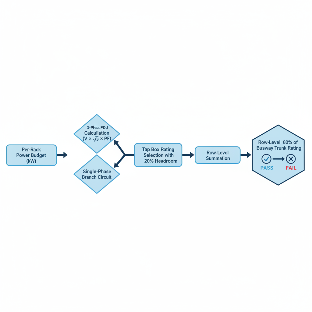
Tap box capacity planning for a data center row starts with the per-rack power budget, works backward through diversity factors and redundancy overhead to determine the required tap box ampacity per rack position, and then sums across the row to validate that the busway trunk rating is not exceeded under realistic worst-case loading conditions.
This is the section of busway tap box power capacity planning that most data center rows get wrong — not because the math is difficult, but because engineers apply general-compute assumptions to high-density environments where those assumptions no longer hold.
The tap box ampacity rating must cover the rack's maximum nameplate power draw divided by the supply voltage and power factor, with a minimum 20% headroom above that calculated value — for a 20 kW rack on a 208V three-phase circuit, this typically means a 32A or 40A tap box per phase is insufficient, and a 63A tap box is the correct specification.
Walking through the calculation explicitly: 20 kW ÷ (208V × 1.732 × 0.92 PF) ≈ 60A three-phase draw. If the tap box feeds a three-phase PDU, the 63A rating covers this load with approximately 5% headroom — which is tighter than ideal. Adding the 20% headroom requirement pushes the specification to 75A, which in practice means selecting the next standard rating of 100A for any rack expected to sustain near-nameplate draw.
The distinction between tap box ratings for three-phase PDU connections versus single-phase branch circuit connections is a point of consistent confusion. A tap box rated at 63A three-phase is not equivalent to a 63A single-phase connection — the per-phase current in a balanced three-phase load is the total current, while a single-phase tap box carries all of the load current on one conductor. Engineers specifying single-phase tap boxes for high-density racks must apply the full rack current to the single-phase rating, not divide by three.
The concept of stranded capacity is also relevant here. Over-specifying tap box ampacity reserves busway trunk capacity that cannot be allocated to other rack positions, effectively reducing the total number of racks the busway run can support. Under-specifying creates a hard operational ceiling that cannot be resolved without physically replacing tap boxes — a task that, in a live high-density row, requires careful coordination and arc-flash protection procedures. Getting the initial specification right eliminates both problems.
|
Rack Power Budget |
Supply Voltage |
Est. 3-Phase Current |
Recommended Tap Box |
Redundancy Note |
|
10 kW |
208V |
~28A |
32A |
A+B: two 32A tap boxes |
|
20 kW |
208V |
~55A |
63A |
A+B: two 63A tap boxes |
|
30 kW |
208V |
~83A |
100A |
A+B: two 100A tap boxes |
|
40 kW |
400V |
~58A |
63A |
A+B: two 63A tap boxes |

The sum of all tap box maximum ratings across a row will almost always exceed the busway trunk ampacity — and that is intentional, because diversity factors (typically 0.6–0.75 in production data center environments) mean not every rack peaks simultaneously; the planning task is to confirm the diversified row load stays within 80% of the busway trunk rating.
The 80% continuous load rule — derived from NEC 210.20 and standard data center design practice — means a 630A busway trunk should not be planned to carry more than 504A on a continuous basis. Applied to a 10-rack row with 63A tap boxes, the theoretical maximum draw is 630A. A diversity factor of 0.7 reduces the realistic peak to approximately 441A, which represents 70% of the trunk rating — within the 80% ceiling with margin remaining for growth.
The critical exception for high-density environments involves AI and GPU compute rows. GPU servers running inference or training workloads operate near their thermal design power continuously, with diversity factors that commonly fall in the 0.85–0.95 range rather than the 0.6–0.75 typical of general compute. A 10-rack GPU row with 63A tap boxes and a 0.90 diversity factor produces a realistic peak of 567A — which exceeds the 504A continuous limit of a 630A trunk and requires either an 800A trunk or a reduction in row length. This is not a theoretical edge case; it is the standard operating condition for AI compute infrastructure, and applying general-compute diversity assumptions to these rows is a planning error with direct operational consequences.
Before energizing any overhead busway installation in a high-density data center, four checks are non-negotiable: insulation resistance testing across all conductor bars to ground, torque verification at every joint and end-feed connection, phase rotation confirmation at the feed unit terminals, and visual inspection of every installed tap box for full engagement with the busway channel.
These checks are where field failures are caught — or missed. A busway run that passes all four checks before energization has eliminated the most common causes of post-commissioning failures. A run that skips any of them carries unknown risk into a live environment where the cost of a fault is measured in downtime, not just repair time.
Insulation resistance testing on an installed data center busway is performed with a 500V or 1000V DC megohmmeter applied between each conductor bar and the grounded housing, with acceptable readings typically above 100 MΩ — values below this threshold indicate moisture ingress, mechanical damage, or a contaminated joint that must be resolved before energization.
The procedure requires testing each phase-to-ground and phase-to-phase combination with all tap boxes removed from the channel. Tap boxes should only be reinstalled after the busway trunk itself passes the insulation resistance test, because a failing tap box can mask a passing trunk or vice versa. All readings should be documented — not just noted as pass/fail — because these baseline values become the reference point for future maintenance testing. A reading that drops from 500 MΩ at commissioning to 120 MΩ two years later is a meaningful signal even if it technically remains above the 100 MΩ threshold.
In facilities that are still under construction at the time of commissioning — which is common in phased data center buildouts — ambient humidity may temporarily suppress insulation resistance readings. Concrete curing, HVAC systems not yet operational, and open building envelopes all elevate moisture levels. If readings are borderline, allow the facility to reach its intended operational temperature and humidity range before making a final determination.
Every tap box must be physically confirmed as fully seated and locked in the busway channel before energization — a partially engaged tap box creates a high-resistance contact point that will arc under load, and in a high-density row this failure mode can cascade rapidly because of the sustained high current levels.
Full engagement verification requires checking the locking mechanism — whether lever, bolt, or cam depending on the busway design — in both visual and physical terms. Visual confirmation that the locking indicator is in the locked position should be followed by attempting to shift the tap box laterally. A properly locked tap box will not move. One that shifts even a few millimeters is not fully engaged and must be reseated before the row is energized.
The sequencing of energization matters as well. The busway trunk should be energized first with all tap box circuit breakers in the OFF position. Tap boxes should then be switched on sequentially — not simultaneously — while monitoring phase current at the feed unit. Sequential energization allows the installer to observe the current increment from each tap box and identify any tap box that draws anomalous current on engagement, which is an early indicator of a wiring fault or PDU problem downstream. At ZHERUTONG, our tap box designs include a positive engagement indicator that provides installers with clear visual confirmation of full seating, specifically to eliminate the partial-engagement failure mode in field conditions where visual access to the busway channel may be limited by overhead working position.
An overhead busway installation in a high-density data center does not exist in isolation — its mounting height, tap box positions, and run terminations must be coordinated with in-row cooling unit clearances, overhead cable tray routing, and the planned positions of future rack additions before the first support bracket is anchored.
In-row cooling units typically occupy one rack unit of row space and frequently have top-of-unit service clearance requirements of 300–400mm. A busway run mounted without accounting for IRU service access may physically prevent a technician from servicing the cooling unit without first removing overhead components — an unacceptable constraint in a live environment. Confirming IRU installation height and service access zones before finalizing busway mounting height adds one coordination step to the pre-installation process but eliminates a recurring operational problem.
Rear-door heat exchangers add 150–200mm to the rear depth of a rack, which shifts the effective center-of-mass of the row and can alter the optimal tap box drop cable angle. In rows where RDHx units are specified, the overhead layout drawing should reflect the modified rack depth so that tap box drop cable lengths are specified correctly — a drop cable that is 100mm too short cannot be field-extended without replacing the tap box assembly.
Cable tray separation from the busway run should be maintained at a minimum of 300mm to avoid electromagnetic interference with data and fiber cabling. In high-density rows where power cables are large-gauge copper and carry sustained high current, the magnetic field around the busway is proportionally stronger, making this separation more important than in standard-density environments.
Finally, future expansion provisions should be built into the initial installation. Specifying busway run lengths that include 10–15% additional tap box positions beyond the current rack count costs very little at the time of installation and avoids the significantly higher cost of extending a busway run in a live environment. At ZHERUTONG, we design our busway systems with open-channel architecture that allows tap boxes to be added at any point along the run without interrupting adjacent positions — a specific advantage for high-density environments where capacity additions happen on compressed timelines.
---
What ampacity rating should I specify for an overhead busway serving a high-density GPU compute row?
For GPU compute rows where per-rack draw exceeds 20 kW, a minimum 630A busway trunk is appropriate for rows up to approximately 10 racks, provided a diversity factor no higher than 0.75 is applied. For rows with GPU servers running near TDP continuously — where diversity factors commonly reach 0.85–0.95 — an 800A or 1000A trunk is typically required. Calculate the diversified row load first, apply the 80% continuous load rule, and let that result drive the trunk rating selection rather than defaulting to the most common specification.
Can I install tap boxes on a live busway during data center operations?
Yes, provided the busway design specifically supports live tap box installation with appropriate arc-flash protection features built into the product. At ZHERUTONG, our data center busway systems are engineered to allow tap box installation without de-energizing the trunk. Regardless of product design, always follow your facility's arc-flash boundary procedures and use appropriately rated PPE — the product capability does not replace the procedural requirement.
How do I handle phase balancing when rack loads are unequal across a row?
Create a phase assignment schedule before installation that maps each rack's expected load to a specific tap box phase position. For rows with mixed server types — some single-phase PDUs, some three-phase PDUs — assign single-phase tap boxes in a rotating A-B-C pattern and document assignments in your power management system. Revisit the schedule whenever rack positions are reassigned, since a phase balance plan that was correct at initial deployment can become unbalanced after equipment refresh cycles.
What is the recommended mounting height for overhead busway above the rack tops in a high-density data center?
The busway should be mounted so that tap box drop cables reach the top-of-rack PDU inlet without excessive slack or tension — typically 300–500mm above the top of the tallest rack in the row. In facilities with cold aisle containment, this height must be reconciled with the containment ceiling panel position through a coordinated overhead zone drawing. The containment structure, not the rack height, is usually the binding constraint in high-density environments with hard-lid containment.
How does open-channel busway differ from fixed tap-off point busway for high-density applications?
Open-channel busway allows tap boxes to be positioned anywhere along the run without restriction, which is critical in high-density environments where rack positions shift between tenant deployments or equipment refresh cycles. Fixed tap-off point designs lock tap box positions at the factory, meaning any layout change requires either a new busway section or accepting a tap box position that doesn't align with the rack it needs to serve. For high-density deployments where the rack layout may change multiple times over the facility's operational life, open-channel architecture is the more practical long-term specification.
---
High-density data center busway installation is an engineering discipline, not a product selection exercise. The decisions made at the pre-installation planning stage — overhead zone coordination, tap box capacity planning, phase sequence scheduling, and commissioning protocol — determine whether the system performs reliably at 80% utilization or creates operational problems that are expensive to resolve in a live environment. At ZHERUTONG, we work directly with engineers and procurement teams to translate project specifications into installation-ready busway configurations.
If you have a high-density data center project in progress — whether you need a capacity planning review, a custom busway configuration, or sample units for evaluation — send your project requirements or drawings directly to our engineering team at rtdq@rtbusway.com. We respond to all technical inquiries within one business day.