Installing a busbar trunking system in a high-rise shaft and installing one across a factory floor are fundamentally different jobs. Industrial buildings introduce challenges that standard installation references rarely address in any useful depth: horizontal runs that can stretch 100 meters or more across a production bay, ambient temperatures elevated by process heat, vibration transmitted through the structure from presses and compressors, and airborne dust that finds its way into every unsealed gap. As ZHERUTONG, a manufacturer that supplies the RT-CKX8 air insulated busbar trunking system to processing plants, assembly facilities, and large-span industrial structures, we see the same field problems repeat themselves on project after project — not because engineers don't know the product, but because most available guidance was written with commercial buildings in mind.
This guide fills that gap. It covers the industrial-specific planning logic that must happen before a single bracket goes up, the step-by-step installation sequence for horizontal runs, the comparison between air insulated bus duct and compact busbar trunking that shapes the initial selection decision, and the failure modes we see most often on factory sites.
Industrial buildings impose unique mechanical, thermal, and environmental demands on a busbar trunking system that standard installation references rarely address — longer horizontal runs, floor-level vibration, and ambient dust require specific support spacing, enclosure ratings, and joint sealing strategies that differ significantly from commercial or high-rise contexts.
The first difference is physical scale. A commercial building riser might run 3 to 4 meters between floors. An industrial feeder run across a single production bay can easily reach 60 to 120 meters, all horizontal. That length changes everything about support design. For most air insulated bus duct sections, support hanger spacing falls between 1.5 m and 3 m depending on section weight and enclosure size — but on a 100-meter run, even a small cumulative error in bracket leveling translates into measurable stress at every joint along the route. Thermal expansion allowances become non-negotiable: a run of that length can expand several centimeters across its full span under normal operating temperature cycles, and without purpose-built expansion joints positioned every 20 to 30 meters, enclosure buckling is a predictable outcome.
Vibration is the second industrial-specific factor that commercial installation guides simply ignore. A factory floor with stamping presses, large motor drives, or HVAC chillers transmits continuous low-frequency vibration through the building structure. Rigid fixed brackets in those zones transfer that vibration directly into the busbar enclosure and, more critically, into the joint connections. In machinery-adjacent zones, spring-type or anti-vibration mounting brackets are the appropriate choice — not a premium option, but a basic requirement.
Ambient conditions in industrial buildings also directly determine the minimum IP rating. A dry, ventilated assembly plant might be adequately served by IP54. A food processing facility, a metalworking shop generating fine metallic swarf, or any environment with water mist from cooling systems requires IP65 or higher. The wrong IP selection is not a paperwork issue — it is a contamination pathway into the enclosure that degrades insulation blocks over time.
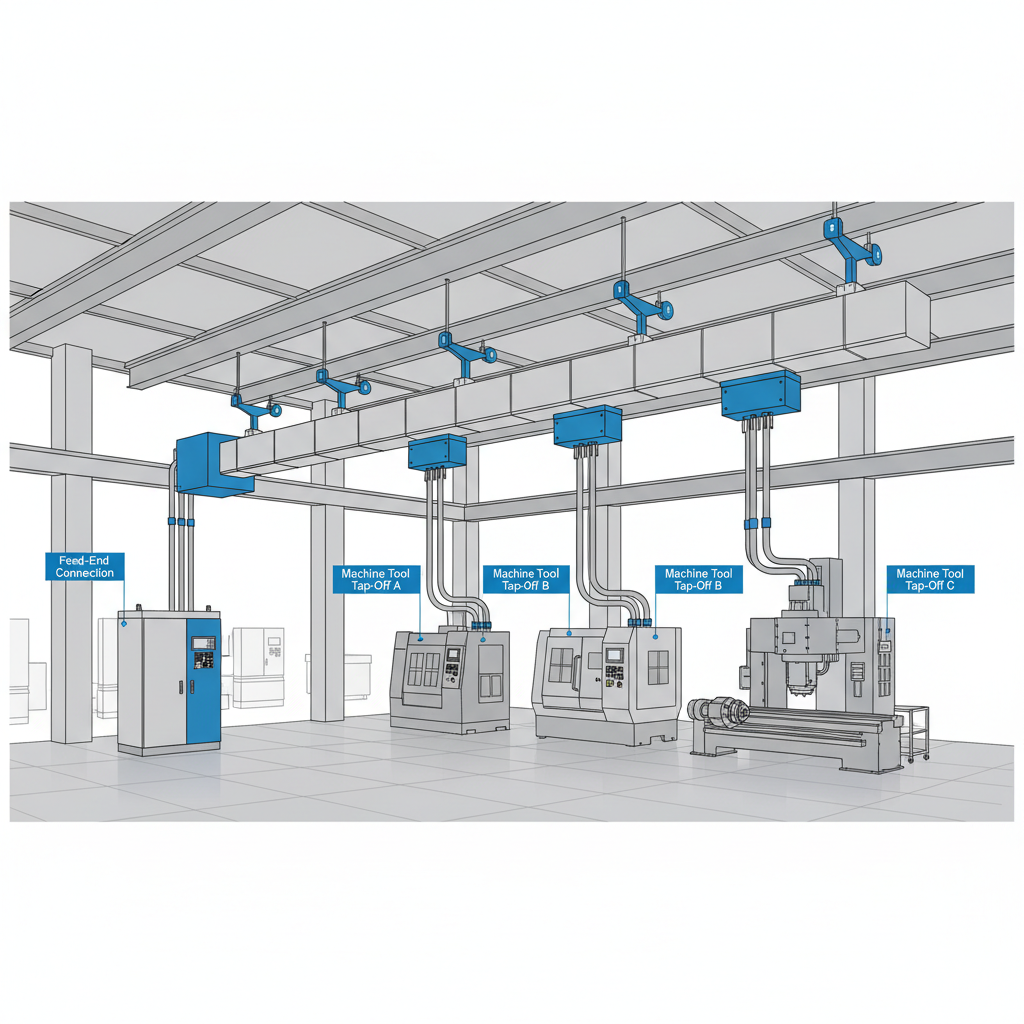
Finally, industrial floors rarely have a simple linear load pattern. Machine tools, sub-panels, lighting circuits, and process equipment tap off at irregular intervals that don't follow a commercial building's floor-by-floor logic. The air insulated busbar trunking system supports current ratings from 250 A to 6300 A, and conductor material selection — copper for high load density and corrosive environments, aluminum where weight and cost are primary drivers — must be resolved at the specification stage, not during installation.
Thorough pre-installation preparation — covering load calculation verification, route survey, enclosure delivery inspection, and coordination with civil and mechanical trades — prevents the majority of on-site delays and rework we see on industrial projects.
A route survey for an industrial busbar installation must map not just the physical path but also heat sources, vibration zones, and load tap-off positions, since all three directly influence enclosure selection and support design.
Start with ceiling height and structural beam positions. Confirm that the proposed horizontal run has adequate clearance for the enclosure cross-section plus the support brackets, and identify which beams will serve as anchor points. In steel-frame industrial buildings, beam clamps are the standard fixing method; in concrete-ceiling structures, anchor bolts set into pre-drilled inserts are used instead.
Map every heat-generating piece of equipment within 2 meters of the proposed route. Furnaces, compressors, and large motor housings all elevate local ambient temperature, which directly affects the current derating factor for the busbar system. A section of the run passing directly over a compressor room may need to be derated or rerouted to avoid operating the system at the edge of its thermal envelope.
Identify all crossing conflicts with pipework, cable trays, and HVAC ducts before the equipment is ordered. Resolving a routing conflict on paper takes minutes; resolving it after sections have been delivered and cut to length is a much more expensive problem. Mark every planned tap-off window position on the routing drawing so that the ordered sections arrive with access windows in the correct locations — this is something we specify explicitly in the shop drawings we provide with every RT-CKX8 project order.
Every busbar section must be inspected for transit damage to the enclosure, conductor alignment, and insulation integrity before any section is lifted into position — damage that goes undetected at this stage is far more costly to fix once the run is assembled.
Check enclosure surfaces for dents, deformation, or cracked paint that might indicate impact damage to internal components. Verify that joint connectors are undamaged and that insulation blocks and phase separation components are intact. Cross-reference each section length against the approved shop drawing — a 200 mm discrepancy in a custom-length section discovered after installation has started is a project-stopping problem. Confirm that the hardware kit for each joint is complete: joint bolts, spring washers, end caps, and earth continuity straps should all be accounted for before any section is lifted. We supply a torque specification table with every shipment, and that document should be on site before installation begins. Using third-party joint hardware instead of manufacturer-original components is one of the fastest ways to compromise joint integrity — the contact surface geometry and bolt torque values are matched to our specific conductor cross-sections.
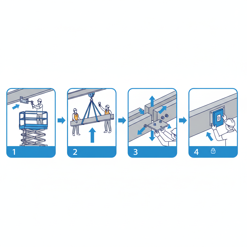
A correctly sequenced installation — starting from the power source end, working outward through support fixing, section lifting, joint assembly, and tap-off positioning — is the single most reliable way to achieve a mechanically sound and electrically safe horizontal run in an industrial building.
Support brackets must be fixed to structural steel or concrete inserts at the specified intervals before any busbar section is lifted, and each bracket must be leveled independently to prevent cumulative misalignment across a long horizontal run.
Mark out all support positions along the confirmed route before drilling a single hole. Account for expansion joint locations — these must be planned into the support layout, not added as an afterthought. For steel structures, beam clamps are torqued to the structural steel before the bracket arm is attached. For concrete ceilings, anchor bolt selection must match the ceiling substrate and the load imposed by the busbar section weight.
Leveling tolerance matters more than most site teams expect. A 2 to 3 mm height variance between adjacent brackets may seem insignificant, but across a 50-meter run with 25 or more support points, cumulative misalignment creates bending stress at joint connections that will eventually manifest as a mechanical fault. Each bracket should be leveled independently using a spirit level before the busbar section is placed on it. In zones adjacent to heavy machinery, install anti-vibration brackets at every support point within that zone — not just at the nearest one.
For sections weighing more than 30 kg per meter, a two-person lift with temporary support slings is the safe minimum — rushing this step is where enclosure damage and joint misalignment most commonly originate on industrial sites.
Position temporary slings to support the section at its quarter-span points, not at mid-span, to avoid loading the enclosure at an unsupported point. Always begin from the feed end — the transformer or main switchboard connection — and work toward the far end of the run. This sequence ensures that each subsequent section can be aligned to the previous one without having to adjust an already-fixed starting point.
Rest each section on its support brackets before attempting to align the joint with the adjacent section. Never try to hold a section in mid-air while simultaneously aligning a joint — this is the single most common source of enclosure damage and phase misalignment we see reported from industrial sites.
Joint assembly is the most electrically critical step in the entire installation — conductor contact surfaces must be cleaned, aligned within tolerance, and bolted to the manufacturer's specified torque value, with no substitutions for joint hardware.
Before assembling any joint, clean the conductor contact surfaces with an approved solvent to remove oxidation, handling oils, and any contamination from transit. Insert the joint pack and verify phase alignment using the phase color coding or markings on the enclosure. Tighten joint bolts in a cross-pattern sequence — not in a circular sequence — to ensure even contact pressure across the full conductor face. The specified torque range for RT-CKX8 joints is 25 to 50 Nm depending on conductor cross-section; the exact value for each section size is in the torque table we supply with the product documentation.
After bolting, install earth continuity straps across each joint. This is not optional and cannot be replaced by a single end-to-end earth conductor — each joint requires its own bonded strap. Fit the enclosure joint covers and verify that the IP integrity of the joint is maintained. A joint that is correctly torqued but has a poorly fitted cover is still a contamination risk in a dusty industrial environment.
Tap-off units must only be installed at the pre-planned window positions marked during the route survey, and the safety shutter mechanism must be tested before the tap-off box is energized.
For plug-in tap-off installation, open the access window at the pre-marked position, insert the tap-off box until it engages the conductor contacts, and lock the mechanical latch. Before energizing, test the safety protective baffle to confirm it operates correctly — this shutter prevents dust ingress and accidental contact when the tap-off box is removed. Connect the outgoing cable from the tap-off box to the sub-panel or machine load only after the latch is confirmed secure.
The choice between air insulated bus duct and compact busbar trunking for an industrial building is not simply about price — it comes down to the available installation space, the ambient environment, the load density, and how the system will be maintained over its service life.
The comparison table below covers the factors that matter most in industrial selection decisions:
|
Comparison Factor |
Air Insulated Bus Duct |
Compact Busbar Trunking |
|
Conductor insulation method |
Air gaps + polyester film wrap + insulation blocks |
Solid insulation laminated directly onto conductors |
|
Enclosure cross-section |
Larger — requires more ceiling clearance |
Smaller footprint for equivalent current rating |
|
Heat dissipation |
Natural air convection — effective in ventilated spaces |
Relies on solid insulation thermal conductivity |
|
Maintenance access |
Enclosure can be opened for visual inspection |
Sealed — condition assessed via thermal imaging only |
|
Suitable ambient environment |
Dry, ventilated industrial interiors |
Better sealed; preferred in dusty or humid zones |
|
Typical current range |
250 A – 6300 A |
400 A – 6300 A |
|
Inter-phase spacing |
Approximately 50 mm |
Minimal — conductors laminated together |
|
Initial material cost |
Generally lower for equivalent rating |
Generally higher |
|
Voltage drop on long runs |
Slightly higher due to greater conductor spacing |
Lower inductance; better voltage stability |
Air insulated is the right call for large-span factory buildings with adequate ceiling height, dry and ventilated interiors, and projects where maintenance teams need direct visual access to conductors for periodic inspection. It is also the more budget-appropriate choice when initial capital cost is a primary constraint and the site conditions genuinely support it.
Compact busbar trunking makes more sense in facilities with significant dust, humidity, or chemical vapor in the air; in installations where ceiling space is genuinely constrained; and on long feeder runs where voltage drop directly affects the performance of sensitive process equipment.
One pattern we see repeatedly on industrial retrofit projects is worth flagging directly: engineers who have specified compact type for high-rise commercial projects often default to the same choice on factory floor work, assuming it is always the superior option. In open production bays with good natural ventilation, accessible ceilings, and maintenance teams capable of periodic visual inspection, the air insulated busbar trunking system frequently delivers better long-term value — lower initial cost, simpler maintenance, and easier modification when machine layouts change. The site conditions, not the product hierarchy, should drive the decision.
Most field failures in industrial busbar installations trace back to four avoidable errors: incorrect support spacing that allows mid-span deflection, undertorqued joints that develop resistance over time, missing earth continuity across joints, and tap-off units installed at unplanned positions that compromise enclosure integrity.
Exceeding the maximum support span is the most visible error. When a section sags at mid-span, it loads the adjacent joints in bending rather than pure compression. Over time, this mechanical stress works the joint connection loose, creating a high-resistance contact point that thermal imaging will eventually reveal — usually after the system has been in service long enough that correcting it requires a partial shutdown.
Undertorqued joints are the most common warranty inquiry we receive at ZHERUTONG. The failure mechanism is straightforward: a joint bolted to 60% of the specified torque has a smaller effective contact area between conductor faces. Under load cycling, that contact area develops micro-movement, oxidation accelerates, and contact resistance climbs. The hot spot that results is detectable by thermal imaging before it becomes a fault, but only if periodic thermographic inspection is part of the maintenance program — which it often isn't on industrial sites until after the first incident.
Earth continuity gaps are a safety issue with direct fault-clearance implications. Each joint must have its own earth continuity strap. A single earth conductor run from one end of the system to the other does not provide adequate bonding at intermediate joints, because the enclosure sections themselves are not reliably bonded to each other through the mechanical joint alone.
Ignoring thermal expansion on runs longer than 20 meters causes enclosure buckling that is immediately visible but expensive to correct after the fact. Industrial buildings experience wider temperature swings than climate-controlled commercial spaces — a factory that drops to near-ambient overnight and heats up under full production load during the day is putting its busbar system through a significant daily thermal cycle.
Finally, energizing before completing an insulation resistance test is the fastest way to discover a damaged insulation block after the system is live. The minimum acceptable IR value for low-voltage systems is 1 MΩ measured at 500 V DC on the completed run before commissioning. This test takes under an hour and provides a documented baseline for future comparison. Skipping it is not a time-saving measure — it is a deferred fault-finding exercise.
---
For most air insulated bus duct sections, support spacing ranges from 1.5 m to 3 m depending on section weight and enclosure size — always follow the manufacturer's specific span table, as exceeding it causes enclosure deflection and joint stress.
The span table accounts for both the static weight of the section and the dynamic loads from vibration. Sections with larger conductor cross-sections and heavier enclosures require closer support spacing. When in doubt, err toward shorter spans — the cost of an additional bracket is negligible compared to the cost of a deflected enclosure.
Yes — in environments with significant airborne dust or metallic particles, the enclosure IP rating must be specified at IP54 or higher, and tap-off window shutters must be confirmed functional before installation to prevent contamination ingress at access points.
In metalworking environments where fine swarf is present in the air, IP65 is a more appropriate baseline. The safety shutter on each tap-off window is not just a safety device — it is the primary barrier against particulate ingress at the most vulnerable point of the enclosure.
Yes, but vertical industrial riser installations require spring-type vertical supports at specified intervals to handle both the system weight and thermal expansion in the vertical plane — the support type and fixing method differ from horizontal industrial runs.
Vertical installations also require attention to the bottom-end fixing detail, which must carry the full suspended weight of the run above it. This is a structurally different loading condition from horizontal support design.
Joint integrity is confirmed through two checks: a torque verification pass using a calibrated torque wrench against the manufacturer's specification table, followed by an insulation resistance test on the completed run before energization.
These two steps should be documented and retained as part of the project commissioning record. They also establish the baseline values against which future maintenance inspections can be compared.
For large, well-ventilated factory floors where ceiling clearance is not a constraint, air insulated bus duct typically offers a lower initial cost and easier long-term maintenance access — compact busbar trunking becomes the more cost-effective choice when dust, humidity, or space constraints are present.
The total cost comparison should include not just material cost but also the maintenance access requirements over the system's service life, which in a well-installed industrial busbar installation can exceed 25 years.
---
Industrial power distribution requirements continue to grow as facilities expand, automate, and add high-density machine loads. Getting the installation right from the first run — with correct support design, properly torqued joints, and a system type matched to the actual site environment — is what separates a busbar installation that performs reliably for decades from one that generates fault calls within the first operating year. At ZHERUTONG, we supply not just the RT-CKX8 air insulated busbar trunking system but the technical documentation, torque specifications, and engineering support that make field installation straightforward.
If you are working on an industrial building power distribution project and need technical guidance, custom section lengths, or want to discuss which system type fits your facility's conditions, send your project requirements, load schedule, or layout drawings to rtdq@rtbusway.com — our engineering team will respond with a system recommendation and quotation.